How to build
a combat robot
We hope this guide will help you turn a pile of components into a fully functional circuit or even a combat robot.
Basic components and wiring
Parts you will need to build a basic robot:
- 2S Lipo battery 120-300 mAh, capacity depends on the type of weapon, rotating weapons require more energy
- Switch, most often a slide switch is used
- Two brush motors with gearbox, most commonly N20, or N10 and N30, rpm 300-1000 at 6V, depending on the required speed and wheel diameter
- Wheels – to minimize slippage, e.g., plastic frame with rubber around it, foam wheels
- Robot frame – the easiest way is to print the frame on a 3D printer, or it can be built from polycarbonate, aluminum, Lego, Merkur, anything that works
Other equipment you will need:
- LiPo charger for charging the battery
- Transmitter and receiver for controlling the robot – Flysky
- transmitter and FS2A receiver
- Soldering iron and solder
- Tools for cutting/removing insulation
- Heat shrink tubing or insulating tape
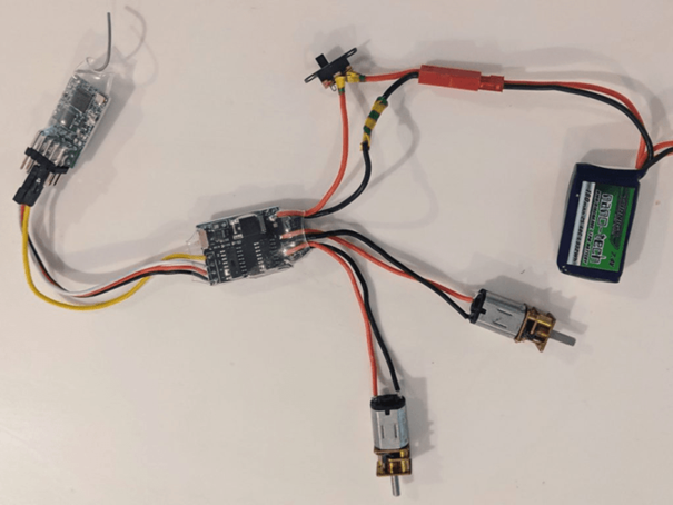
The goal is to connect the components to the following circuit:

If you encounter any problems or have any questions during construction, please email us at info@flsbattlebots.com or write to us on the forum. We will be happy to help you.
Part 1: Soldering motors
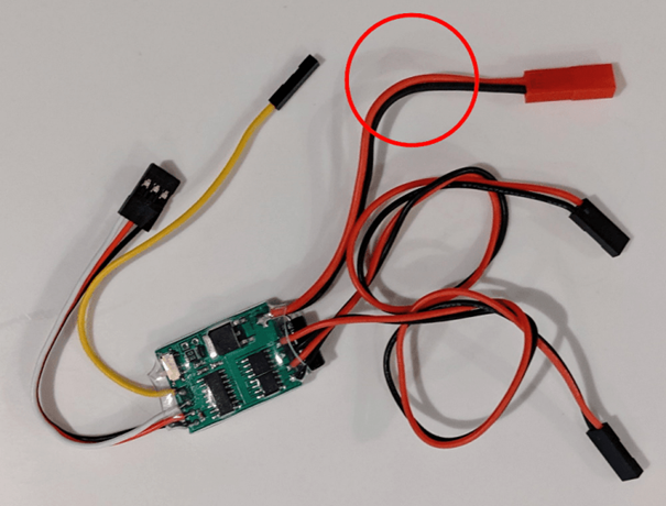
The dual speed controller for brushed motors (ESC) comes with pre-soldered connectors, but we will not be using them in order to save space and weight, so we need to solder the N20 drive motors directly.
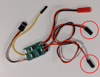
First, cut off the two black connectors in the ring; these are the outputs for the motors. If you want to save a little weight and space, you can shorten the cable. When soldering, check the back of the motors and look for a small plus symbol on one of the motor contacts.
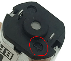
It is worth soldering the motor contact on the positive side to the red wires of the ESC output on both N20 – this means that they will rotate in the same direction when we want them to!
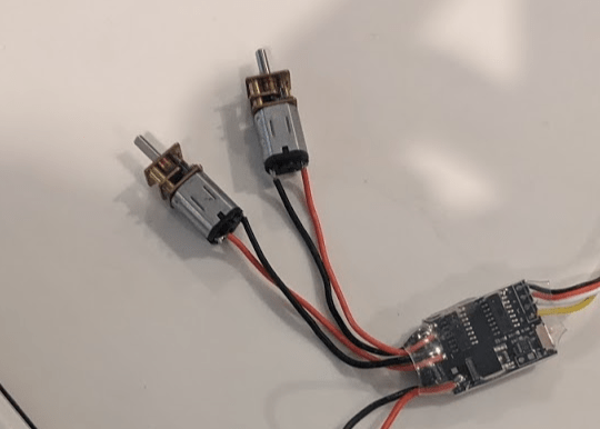
So remove a piece of insulation from the end of each of the four wires and solder each pair of red and black wires to the contacts on the N20 motors – make sure you have the correct two wires for the motor – one pair is marked M1 and the other M2 on the ESC circuit board.
Part 2: Soldering the switch
This is optional, but it is good practice to have a way to turn the robot on or off, other than disconnecting the battery.
1. First, cut the red wire in the ring, but leave the black wire as it is.
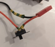
2. Remove a small piece of insulation from each side of the red wire and solder one end to the outer pin and the other end to the middle pin of the switch. Use heat-shrink tubing or electrical tape to cover the pins and exposed wire.
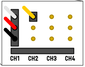
3. Connect the unused ESC cables to the FS2A radio receiver as follows. This completes the basic circuit.
Instructions on how to set up the transmitter and receiver and add weapons to the robot will follow soon.